Overview
This post will describe the process used to identify the Application Processor's (AP's) UART on the Samsung Chromebook as well as enough information to allow others to utilize it for additional research and development. Figures 1 and 2 show the top and bottom of the board with some of the more interesting components and connectors identified. The SoC used in the Chromebook is the Samsung Exynos 5250. It's datasheet [1] has thankfully be made publically available along with a development kit [2]. iFixit has a great tutorial for how to disassemble the Chromebook [3]. As a side note, when disassembling the Chromebook use hotel or credit card to pry the bottom of the case apart if you don't have the same tool that iFixit uses; using a flathead screwdriver will most likely mutilate the case.
Just so the normal disclaimer is here, "I will not be held responsible for any damages caused to you or your device as a direct or indirect result of recreating the results described in this post. Performing this type of modification incorrectly could permanently damage your device."
 |
| Figure 1: Chromebook Board Top View |
 |
| Figure 2: Chromebook Board Bottom View |
The board scan was provided by Panicopticon.
Before diving into where the AP's UART pads are located on the board I want to briefly describe the thought process behind discovering these types of connections.
The Samsung Chomebook has many unpopulated pads available. These unpopulated pads represent both unused functionality (e.g. 3G modem connection), debugging interfaces and test points used for verification during the manufacturing process. These pads are sometimes accompanied by a silk screen that describe the purpose of each pad or at least a set of pads (e.g. LPC debug, USB). Sadly, the Chromebook does not have a silk screen printed but has many unpopulated pads and connectors. This means identifying the UART or any other connection (e.g. SPI, I2C) is left to a semi-brute force approach.
In order to find the specific connection a couple of tools are required, either a logic analyzer or oscilloscope. A logic probe can be used to identify any pin or pad that is transitioning between states (i.e high and low); it will not be useful for protocol analysis but weeds out connections that are constant. These tools can be used to connect to any of the pads exposed and sample its signal (see figure 3). In some situations the tool is to large to contact a single pad; consider attaching a push pin or needle to get a finer contact point.
 |
| Figure 3: Sampling a Pad's Signal |
I chose to use an oscilloscope as it is was available and probably the easiest to work with for quick analysis. I am really only interested in pads that transition or at least ones that are capable of transitioning, as they are the ones that have the potential to transmit or receiving data. In general, any pin that is held low should be checked with a multi-meter to see if it is wired to ground. This will completely eliminated many pads from the potential list. Anything that is head high should have its voltage check and compared with the specific protocols specification. Specifically, UARTs usually operate at either 1.8 volts or 3.3 volts, so anything operating at one of these voltages can be considered a good candidate for further investigation.
Unfortunately, the AP's UART on the Samsung Chromebook was not very active, U-Boot prints "U-Boot SPL, board rev 0" and the Linux kernel prints "Uncompressing Linux... done, booting the kernel.". Once the system is booted the available device nodes (i.e. /dev/ttyS0 through /dev/ttyS3) when accessed reported back "Input/Output error". Due to the fact that the UART wasn't that active on boot and the device nodes produced an errors, I constructed a kernel module to print the state of the UARTs, wrote a byte to the TX FIFO and finally read a byte for the RX FIFO. Figure 4 shows the register layout of the UART.
 |
| Figure 4: Exynos 5250 UART Register Layout |
I quickly found out that the only UART initialized was UART 3 the others reported their uninitialized state. This implied to me that some code either in the OS or bootloader modified the settings to use UART 3. This could mean it was being actively used or just previously used. It doesn't automatically mean the UART was for debugging, although it was, it could be used for something else, such as communicating AT commands to/from a baseband processor.
Hardware
Now that some software was available that transmits and receives bytes from the UART, an oscilloscope was connected to a potential UART's TX line pad. Once connected the kernel module was executed. This process was repeated numerous times until a pad was identified transmitting data on the display of the oscilloscope (see Figure 5) when the kernel module was executed.
 |
| Figure 5: Oscilloscope Display when a UART TX Line is Transmitting |
Once the TX line was found I moved on to finding the RX line. It can be a bit more cumbersome to find if it isn't accompanied by a TX line because it doesn't actively transmit a signal. The RX line is held high, usually either at 1.8 or 3.3 volts, so anything not held high can be eliminated as a potential candidate for the RX line. In general if you know where the TX line is the RX line will most likely be very close (usually directly next to the TX line). Identifying the RX line is much easier with the kernel module I constructed. it continually transmits a byte and then polls the RX line. So, I just create a loopback connection (i.e. connect via a wire, the TX line to the RX line). This will cause the kernel module to display the same byte transmitted in the receive buffer and ultimately in dmesg (the module uses printk to display relevant UART information).
Figure 6 shows both the TX and RX pads for the AP UART. The TX line is pad 3 and the RX line is pad 2 when counting in from the bottom of the 6 pad connector.
+UART.png) |
| Figure 6: Samsung Chromebook Application Processor (AP) UART Pads |
The final line I need to identify is GND. This is very easy to do, I just took a multi-meter and set it to check continuity. I then touched one end to the casing of a USB port and searched the board close to the UART for a GND. Once found the multi-meter beeped. The GND should be close to the UART connectors itself but does not have to be on the same connector. I selected a GND line that was be a bit easier to solder.
Now that the lines have been identified the tricky part of soldering these tiny pads begun. First off if trying to recreate this connection don't try to do this with a crappy soldering iron. It just doesn't work out. Either you'll melt the pads and board or worse yet get really really frustrated. I'm not saying you need an expensive soldering iron but you need one that has a temperature control (a knob with fine grain control not a low high switch) [4]. The tip that comes with the iron is most likely fine but I choose to use a 3mm bevel tip [5]. I have watched multiple videos of people suggesting this tip for surface mount work. Although it has a rather large contact area it works well for this type of work. When soldering I had the iron set to about 300 degrees Celsius and coated the pads with liquid flux [6]. The solder I used was 0.031 gauge leaded solder [7].
To wire these types of pads I used wire wrap wire [8]; it's a 30 AWG wire. This wire is used to make the connection with the pad and then pinned down to the board with hot glue (see Figure 7).
 |
| Figure 7: Solder and Hot Glue Result |
For the GND wire I chose to use a pad from the SD card slot connector, which is located on the opposite side of the board from the AP's UART. It was much easier to solder than the GND pad next to the UART's TX and RX lines (see figure 8).
 |
| Figure 8: Ground Connector |
 |
| Figure 9: Wire Wrap Wire to Jumper Wire |
I again hot glued the wires down to the board, which will further eliminate potential motion and stress from the wire wrap wire. The larger wire is a female to female jumper wire [9] with one end cut off. The end with the connector cut off was the one soldered to the wire wrap wire. The end with the connector will be used to attach/detach a UART to USB adapter [10], as needed. The jumper wires are then ran out the SIM card slot. I cut the slot with pliers so the wires would fit (see figure 10).
 |
| Figure 10: Modified SIM Card Slot |
Don't worry about the additional 2 wires they will be discussed in another post and not important here. So, now I have the TX, RX and GND lines ran out of the case in a clean durable way (see figure 11).
 |
| Figure 11: Chromebook with a UART connector |
Next I wanted to connect the jumper wires to a UART to USB adapter and then plug it into another computer. To do this I soldered on male headers [11] to the adapter (see figure 12).
 |
| Figure 12: UART to USB Adapter with Headers |
Now I was ready to connect the AP's UART to the adapter. If recreating this setup remember that the RX line should be attached to the TX line on the adapter and vise versa. The GND line should be connected and the 3.3v pin is left unpopulated, as the adapter will be powered by its USB port (see figure 13).
 |
| Figure 13: Chromebook AP UART Connected to a UART to USB Adapter |
Software
Now that the adapter is connected to the Chromebook and another computer, open a serial console application. I prefer minicom so I will show how to setup the UART with it. At a terminal type "sudo minicom -s", press <enter>, then enter your password and press <enter> again. This this will start minicom in setup mode (see figure 14).
 |
| Figure 14: Start minicom in setup mode |
Once started the screen in figure 15 will be displayed. Select "Serial port setup" and press <enter>.
 |
| Figure 15: minicom Main Setup Screen |
Now the screen in figure 15 will appear.
 |
| Figure 16: minicom Serial Port Setup Screen |
Change the Serial Device by pressing <A>, typing "/dev/ttyUSB0" and then pressing <enter>. Next change "Bps/Par/Bits" to 115200 8N1 by pressing <E> and then selecting the the correct settings, once complete hit <enter>. Press <enter> again to save the settings and return to the main setup screen. Now select "Exit" and press <enter>. minicom should now present the serial console (see figure 17).
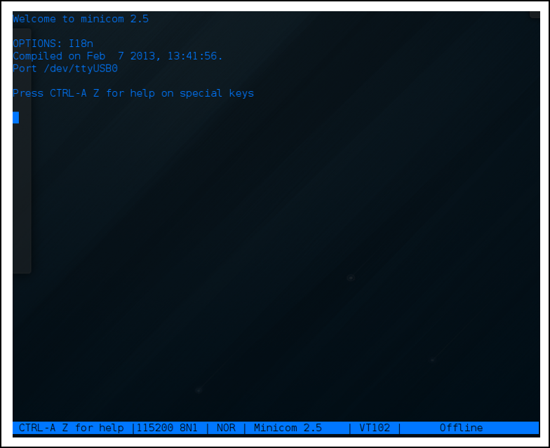 |
| Figure 17: minicom Serial Console |
If you power on the Chromebook two messages will be displayed one that shows U-Boot loading and another when execution is passed to the OS (see figure 18).
 |
| Figure 18: AP UART Boot Messages |
The previously constructed kernel module was executed to show the UART working. When the module is running it is continually polling the RX buffer for bytes so when I held down a key in minicom the key was displayed in dmseg on the Chromebook. minicom continually showed the byte written to the TX buffer in the kernel module on the Chromebook.
Conclusion
This post will hopefully allow others to find and connect to the Chromebook AP's UART. It should be useful for people doing low level research and development with the Samsung Exynos 5250. For reference all of the truly relevant information is in Figure 6. It contains the hardware pad locations and serial configuration. The Chromebook has many interesting features including a ARM Cortex-A15 CPU with the Virtualization Extensions (VE), a TPM and an Embedded Controller (EC). For these reasons along it is exciting to provide access to this essential debugging interface.
There was one other thing I wanted to mention. This is not the only UART exposed by unpopulated pads on the Chromebook! The EC has one and it provides a very interesting interactive console. The EC's UART and console will be discussed in another post.
If you are interested in having this setup on your Chomebook but do not feel comfortable performing the hardware modifications or just have questions feel free to contact me at [de7ec7ed <@> gmail.com].
Links
[1] Samsung Exynos 5250 Datasheet[2] Arndale Development Kit
[3] iFixit Samsung Chromebook Teardown
[4] Soldering Iron
[5] 3mm Bevel Soldering Iron Tip
[6] Liquid Flux Pen
[7] Solder Leaded
[8] Wire Wrap Wire
[9] Jumper Wires
[10] UART to USB Adapter
[11] Straight Breakaway Header
Add a comment